With no need for output arms/wheels, clevises, keepers, pushrods, set nuts, threaded couplers, horns, back plates,
ball links/sockets, exit guides, bumpy servo covers, etc. deflecting a surface is simplified.
G2 SYSTEM MISSION STATEMENT: “To make wings clean, stealthy, more beautiful and without the parasitic
drag of external hardware, able to perform at their maximum aerodynamic potential.”
The concept popped into mind in ’88 after I became disenchanted with hardware hanging out of my otherwise
beautiful sailplane wings. The big issue was firmly attaching the shaft to the output gear and making it easy to install,
adjust and service. Nothing tried worked well. In ‘99 an injection-molded “coupler” was designed in collaboration
with Kimbrough Racing Products, Inc. It worked with solid wire shafts, but was not easy to install and had its limitations.
I called it the Rotary Driver System. It had limited publicity only in sailplane articles and was never effectively advertised.
This brand new “G2 SYSTEM” is a highly-refined, meticulously-made version of the RDS for use in
all kinds and sizes of RC planes with ailerons, flaps, flaperons, elevons, etc. Its unique design features are the
result of collaboration with Kimbrough and modeler-machinist Walt Dimick of IRF Machine Works, Inc., who has long provided
a fine line of RC accessories, including for the old RDS.
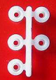
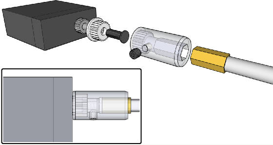
Here’s what the installed hardware looks like: (LEFT) as viewed from a top hinged aileron and (RIGHT)
as viewed from a bottom hinged flap. No hardware hangs out!
This picture shows part of the wide array of new hardware available exclusively through IRF Machine Works owned by modeler-machinist
Walt Dimick. All items are available a la carte.
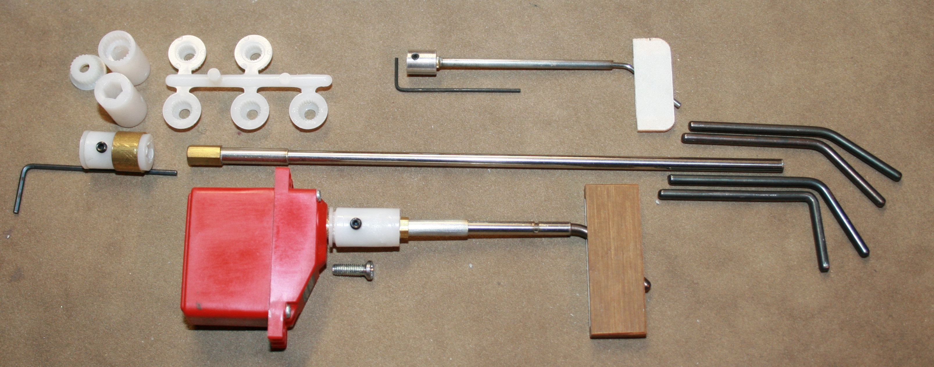
The front-splined “coupler” comes with a tree of adapters to fit popular servos. Its single 4-40 set screw
is captured behind an “Auxiliary Servo Screw” (foreground above) to firmly secure the coupler. The coupler easily
attaches, detaches and adjusts rotationally. Pre-assembled, hex-ended, rigid SS hypo tubing “drive shafts” slide
into and in it. Shafts come 6” long to custom trim to length. The bent “wipers” fit “pockets”
with a precise “slightly snug” fit. For small craft, such as DLG’s, there’s a 1/8” hex-fitted
coupler/shaft and other parts. For additional pictures and information, see the separate documents G2 Pricing and Pre-Ordering Work Sheet and Generation 2 RDS & DLG’s.
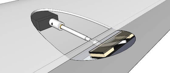
These “see through” drawings, courtesy of modeler-software engineer Duane Beck, illustrate how pocket and wiper
go in a hinged surface and how the coupler interfaces the servo and shaft assembly.
Our modeler-mechanical engineer friends have established that a well-designed, properly-installed RDS, with its minimal
moving parts, minimizes sources for slop and wear. As a testament to RDS viability in a demanding environment, world class
fliers involved in international F3B, arguably the most demanding of all major competitions, have gone almost exclusively
to expensive, custom-machined forms of it in those highly-refined airframes. Higher-end molded airframes are being offered
with the hardware pre-installed.
My experience with the set screws for shaft retention, as used on the ’99 Kimbrough coupler, is that they don’t
secure a round shaft well even with opposing flats ground on it. They can get loose in those unscheduled hard dorks and if
flaps are dragging on landings. The coupler threads can strip out or the coupler can split if the setscrews are over-torqued
in seating them in colder weather. The G2 System coupler eliminates them and for heavy duty applications, a reinforcing brass
sleeve is available to press over the rear end of the coupler. The setscrew in the new coupler retains it on the gear by being
captured behind a flat headed Auxiliary Set Screw. It does not bear on the drive shaft.
G2 hardware from IRF Machine Works is very reasonable in cost and if you make pockets as I’ve done for years (see
document Making Your Own Pockets ) the cost for the other hardware is very modest.
For those interested, http://www.hauninger.gmxhome.de/hobbies/modeling/RDS/RDS.html has technical discussion, graphs, tables, formula, etc. that relate all the
variables involved. It may be surprising to know how little you really need to know to do a proper installation, simply following
the instructions below.
PRACTICAL SUGGESTION: Review the document G2 Pricing & Pre-Ordering Work Sheet to help make decisions about what parts to order. Go go http://www.irfmachineworks.com/ to order.
The new G2 System is far easier to install than with the original Kimbrough couplers made for solid drive shafts. I did
installations in over 50 ships and became well aware of the difficulties and limitations involved. The new coupler and new
drive shaft design have greatly simplified an installation. While I’m a sailplane flier, the installation procedures
are common to all kinds of aircraft and the wide array of hardware available makes it suited to most any size and kind of
RC aircraft.
G2 System Installation Instructions
Installation is different than for the horn/clevis/pushrod, but certainly not difficult. Do it
once and it will become routine like everything else you once didn’t know how to do. With the new hardware and “how
to” instructions that follow below, installation has never been as easy or straightforward.
Below is a list of supporting documents. Left click to open any document
|
|
The drawing illustrates an installation in a typical ARF wing. to the As needed to access the set screw, shift
the servo in a hollow wing. In a foam wing, remove some core between the skins.
To connect/disconnect the coupler from the output gear or the hex ended shaft from the coupler requires space
to separate them up to 5/16”. Sliding the servo toward the LE, sliding the wiper some behind the pocket or some combination
of both will do it.
Sliding calls for a servo with side mounting lugs or removing lugs to secure the case between rails with a bracket
or plate as done in the document Harley’s Easy Mounting System (HEMS).
|
It would be more convenient to install the G2 System in ARF wings if the openings were angled and made longer, something
to anticipate in ARFs designed to best utilize any RDS.
See drawings and pictures that follow and the RELATED PICTURES AND DRAWINGS pages. www.irfmachineworks.com (modeler-machinist Walt Dimick) offers all G2 parts. See the
Pre-Ordering Pricing and Work Sheet in the Genie pages for parts description and pricing.
|
|
Flap servos must be angled and wipers bent enough to get liberal down flap. Aileron servos may be angled or squared-up.
Shaft lengths vary with servo location and wing chord.
|
SHAFT ANGLES: Studies have established that shafts angled at 50 degrees to the hinge line give best mechanical
trade-offs. In RELATED PICTURES AND DRAWINGS, refer to Drawing #1 to see how modeler Tuan Le fitted flap servos at 50 degrees
into an ARF wing with small, squared-up openings.
At the 50 degree angle, the table below illustrates relationships between wiper bend angle and deflection for a 90 degree
rotation of a flap servo and 50 of an aileron servo. It’s assumed hinging, gap seals, other structure or radio limitations
don’t prevent the indicated deflections.
|
|
|
|
|
|
|
|
|
|
|
|
|
|
|
|
|
|
| |
|
|
|
|
|
|
|
AILERONS, WIPER BEND ANGLE
|
|
|
|
|
|
|
|
|
|
|
|
|
|
|
|
|
| |
|
|
|
|
|
|
|
AILERONS, SHAFTS AT 90 DEGREES TO HINGE LINE
|
|
|
|
|
|
|
|
Using a wiper with a smaller bend angle equates to using a closer-in hole in an output arm. Power and resolution
are improved. Where practical, use a smaller bend and more servo rotation/stick travel.
DOUBLE-SPLINED ADAPTERS: From trees, locate ones specified. If not specified, check for a fit.
No fit? See Genie pages document “Custom Splining the Coupler” or use servos known to have a fit.
|
|
LEFT TOP: Std. Hitec, Volz Alu-Star. LEFT CENTER: Std. Airtronics, JR, Multiplex, Sanwa. LEFT BOTTOM: Std.
Futaba, FMA series 300, Std. Dymond. RIGHT TOP: Std. Volz. MKS 6125 (tight fit). RIGHT BOTTOM: FMA 88/90/95/100,
etc. Cirrus CS 20/21, MPI MX 30.
|
|
|
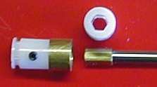
The 3/8” x 5/8” coupler with its single set screw is shown with a partially inserted adapter, set screw, brass
reinforcing sleeve for heavy duty applications and the 3/16” x 3/8” hex end of a drive shaft. Nicely squared up,
tap the set screw hole with a 4-40 tap or any longer 4-40 screw.
|
|
|
COUPLER SECURING: The coupler set screw is captured behind an Auxiliary
Servo Screw 1, 2 or 3. See the PROGRAMMING and FINISHING THE INSTALLATION paragraphs on page 4 about dealing with these screws
and with servos using a sheet metal type screw in a plastic gear.
|
BENT WIPERS: IRF makes these from precision-ground tool steel drill stock, bent at needed low radius, then hardened
and tempered. The surface gets oxidized in the process. To mark on it, wet sand the long end to bright steel. Wipers are made
“STANDARD”, specified as .104” and “HEAVY DUTY” specified as .1285” with stock bends of
85, 62, 45 and 30 degrees. Custom bends are available.
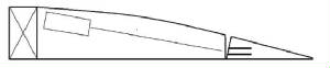
Exaggerated, the drawing below depicts a common situation of the servo/mount being attached to the top skin
and the pocket lower in the hinged surface. Since coupler and shaft are rigid, the servo/mount has to be tilted to direct
the shaft into the pocket. Tilting is easily done with a wedge, glob of epoxy putty, silicone sealer, etc. under the servo/mount.
Have everything in place as the adhesive cures.
To make installation more convenient, perhaps some servo frame maker will make a sliding mount for G2 System
installations and ARF makers will make wings with better oriented and configured servo openings. ARF wings could be made with
a tilted area where the servo goes. Then pockets could be placed between the skins to best align to the shaft in profile view.
SERVO LOCATION/OPENING CONFIGURATION: If the wing is hollow with openings pre-made, there’s leeway
in locating servos between the skins. Given that clear, thin, flush mounted plastic servo covers (Page 5) can be used, it
may be practical to reconfigure an opening to make installation more convenient. If the wing allows cutting openings or if
the modeler is making it, openings can be cut for most convenience. See Genie pages Const. File 3, Part 2. Decide where a
servo is to be located with ample headroom and so it can be slid toward the LE.
SHAFT PATH: On which to mark the path, whether angled or squared up, apply low tack masking tape on the
wing bottom and in the general area where the pocket is to go. Mark the path on the tape. Align the wiper long end
to the marked path. Position the pocket so the wiper short end clears it’s inside edges.
IRF POCKETS: Spacers between tops and bottoms are precisely machined for a uniform “slightly snug”
fit on the order of .001” less than wiper diameter. This avoids surface buzz at higher speeds. A given length of the
steel drill stock used will vary as much as .002” in diameter. If some IRF wipers seem too tight compared to others,
there’s an easy custom fix. Using #320-400 wet or dry paper wetted, wrap it around a block. To the wiper sides that
lay flat, make 10 passes on each side and recheck the fit. Repeat until it feels “slightly snug”. See the document
“Making Your Own Pockets” to cut cost. Use epoxy as the adhesive when installing pockets, but keep it out of the
wiper opening!
|
|
Mark where the pocket recess should be made. If there’s space, use balsa shims over and under the pocket. Assembled
pockets can be thinned to get them fully recessed.
|
If the surface is beveled for deflection, similarly bevel the front of the pocket. Before installing a pocket,
wrap its ends with single layer of fine thread, preferably Kevlar. If possible, make clearance behind the pocket so the wiper
can be moved there to facilitate separating the shaft hex end from the coupler or the coupler from the servo. If a “reusable
insert” is provided with IRF pockets, lightly wax it to keep top/bottom in perfect parallel planes while installing
pockets. Keep all flat as the epoxy cures. In the main Genie pages, See Const. File 3, Part 2, page 5-6 about recessing and
securing pockets.
HONING THE HEX FIT: Slight manufacturing variations in the brass hex diameter impact the sliding fit with
the coupler. If tight, touch up faces with a flat whetstone. The 3” triangular Bear Paw Tackle Co. Fish Hook Sharpener
used wet and flat, works well. Mark shaft where you start. Count strokes to do faces uniformly. A proper fit will allow sliding
without unwanted rotation inside the coupler. Bevel the hex brass front edges to get it going into the coupler.
SIZING A SHAFT TO LENGTH: Seat an adapter on the servo and a coupler on the adapter. Invert the wing. Place
a servo in its intended location. Along the shaft path superimpose the shaft hex end ¼” over the coupler. Mark the shaft
¼” ahead of where it intersects the hinge line. Cut it there. Put ID on the shaft. Repeat for all wing servos.
HINGE LINE HOLE: Through hinge line structure along the shaft path, progressively make an opening opposite
the pocket plane large enough to insert the shaft hex end. If pre-hinged, deflect surface for access. If gap seal is in the
way, remove a little of it. The hole allows “float”. Its edges control lateral play.
“SWEET SPOT”: This is the wiper elbow location relative to the hinge line that allows smooth,
easy deflection. For flaps, it’s typically wiper diameter behind the hinge line and for ailerons, that ahead of it.
ATTACHING THE WIPER: See listed document about Silver Soldering IRF Wipers & Shafts or use the black, rubber-toughened CA glue such as the
Bob Smith Industries IC-2000. One servo at a time, do this: Place the servo/coupler in its intended location. Superimpose
the shaft hex end ¼” over the coupler. Slip a wiper into the shaft to put the elbow at the mentioned typical sweet spot.
Mark the wiper where it exits the shaft. Attach the wiper. Repeat for all shafts. Shafts will be installed after programming
is done.
INITIAL PROGRAMMING: Pick a setup. Program out all throws for the wing servos. If the wing has ailerons,
proceed with one of those. Put the related trim tab in neutral. Program the servo to its neutral. Turn radio off. Holding
the servo in the hand, oriented as it will be mounted with wing inverted, fully seat an adapter on the output gear. Run the
Auxiliary Servo Screw in leaving 1/8” of the threads exposed.
Slip on a coupler so its set screw is essentially pointing straight up. Fully seat coupler on the adapter and
thread in the set screw to just touch the Aux SS threads. Then back off a hair. From the coupler hex end, screw in the AUX
SS to take up any slack with the set screw. This firmly secures the coupler to the output gear with no set screw bearing on
it. As needed with radio on, program the Tx to get the wiper perfectly horizontal. Repeat this sequence with all wing servos.
Flap “neutral” means no up or down flap.
GETTING THE SHAFTS IN: If the moving surface is not pre-hinged its pocket can be slid over the protruding
wiper when later hinged. If pre-hinged, if the wing is hollow and if the wiper bend angle is small it may be possible to manipulate
the wiper into the pocket working through the servo opening. If not, make the hinge line hole into a horizontal groove or
depression deep enough to get the shaft/wiper forward enough to close the pocket over the wiper.
|
|
This servo is “HEMS” mounted with a bracket. See the document Harley’s Easy Mounting System. Taller rails could be used and a plate cinched down
on the case with screws. Note space for sliding, the accessible set screw and that about 3/32” of the hex brass is exposed
to allow “fore-aft” sliding on deflection. Foam behind the pocket was also cleared out so it was easy to separate
the coupler from the servo or the shaft from the coupler. Using long drill bits and round files, a path for the shaft was
tunneled through the foam from the hinge line to the coupler. It’s even easier in a hollow wing.
|
FINALIZING THE SWEET SPOT: Run the shaft hex end ¼” into
the coupler. Slide the servo/coupler/shaft assembly to put the elbow where the surface can be manually most easily deflected.
That’s the spot! Position the servo to retain it. If necessary, redo the joint to adjust shaft/wiper length.
The elbow automatically stays put at the sweet spot although it can meander a bit through the deflection range.
FINAL PROGRAMMING: Observe
which direction the servo/wiper is to move to deflect the surface in the intended direction. Program in some throw. Check
that rotation is correct with the related stick or lever. Finish setting end points. Repeat the sequence for all servos.
FINISHING THE INSTALLATION:
If a sheet metal type servo screw is used, find a Phillips head flat headed longer one the same diameter. Grind down the head
to narrow it to slip into the coupler.
|
|
FLUSH SERVO COVERS: Barely visible here, for easy inspection and to demonstrate the installation, use clear, thin
plastic sheeting attached under its corners with double sticky clear tape. Pull about 1” of the tape beyond the dispenser
serrated edge, scissor off smudged part, overlap a corner of the cover on it, press lightly with Popsicle stick, etc. scissor
off & trim. Repeat on all corners. Press in place.
|
REMOVING A SERVO &/OR SHAFT FOR SERVICE: Separate servo and shaft enough to get the servo out. To
get the shaft/wiper out, the wiper must be slipped out of the pocket in the hinged surface. If a groove was made ahead of
the hinge line to get the wiper into the pocket in a pre-hinged surface, recess the wiper into it to deflect the surface
to get it out of the pocket. Deflect the surface to then pull the shaft/wiper out of the wing. If there’s no
groove for recessing, make one.
If surface play is present or develops, one or more reasons may be listed below.
-
There’s slop in the servo gear train.
-
The surface itself is flimsy or flexible.
-
The servo, its mount or a bracket is loose.
-
Hinging allows play between wing and surface.
-
An adapter seems to fit an unspecified servo but the two are differently splined and allow slippage.
-
The pocket is loose.
-
The pocket has split.
-
The coupler has split in a hard dork or from flaps dragging.
-
The hex brass was over-honed.
-
The “slightly snug” fit between wiper and pocket is not snug enough.
Puff a little dry keyhole lubricant into the pocket. A compressed air canister will clear out dust and debris.
|